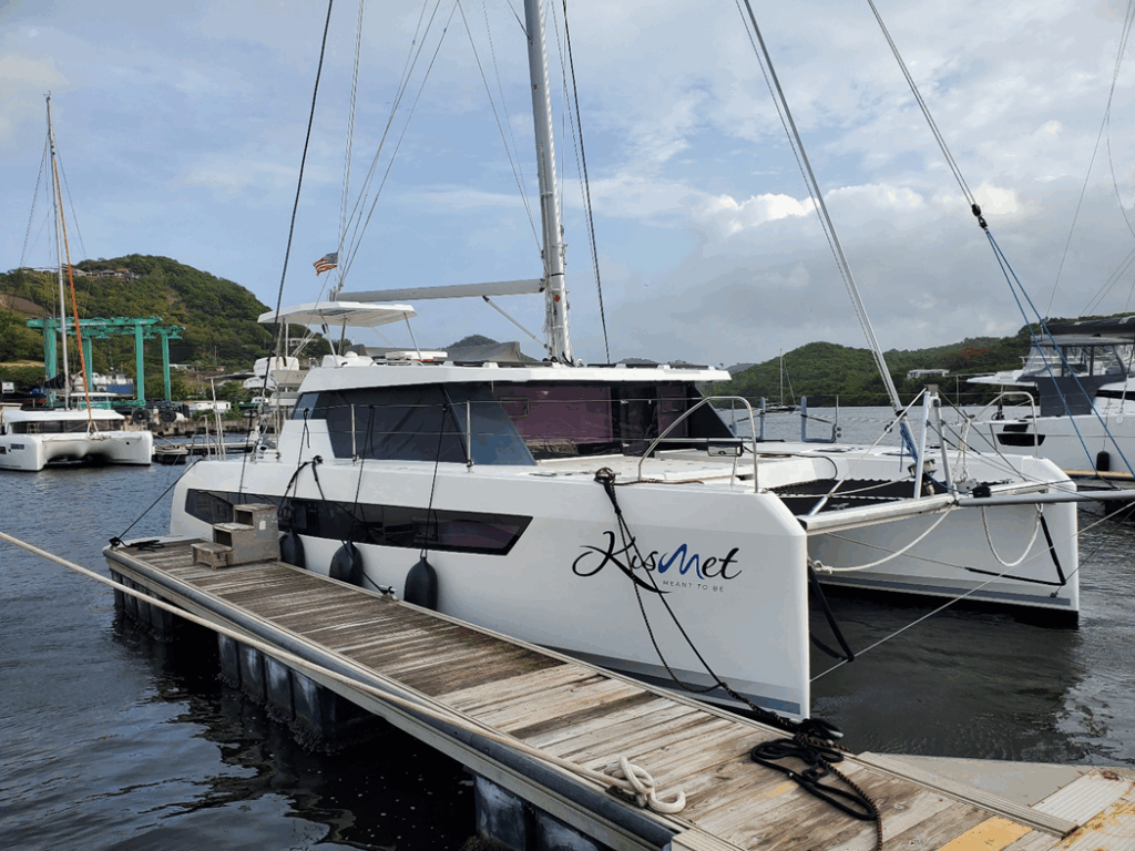
**Kismet. Photo credit: Colin Chapman**
Overview of trip
The client’s Leopard 42 has previously been upgraded to four LiFePo4 batteries with an inverter charger and other modifications. The goal was to upgrade the stock Yanmar alternators, to high output alternators to top up the batteries while under engine power.
Arrival and Inspection
Flying to Grenada from Toronto meant no tools or supplies, just my wits and good looks. Well my wits anyway… I had to rely upon the local chandeleries for their support and supply stock levels pertaining to the job at hand.
Day one was the inspection procedure to see what we were dealing with. Each engine bay was inspected and documented for space and current wiring to the stock alternators. Wire routing was determined and the approximate length to the batteries and back calculated to comply safely with ABYC standards. Locations were found for adding shunts, fuses, sensor wires and so on.
Fortunately for us, a sister ship was on the hard so we could inspect it as well. This boat already had our products mounted making this part of the job easier. Being able to compare the two boats, noting differences and similarities with respect to the battery wiring and charging from the alternators would speed up the proof of concept I had developed based on the original boat wiring diagrams.
Once we were happy with our inspection, measurements and picture taking we sat down and made a list of supplies we would need. Wire, several different sizes and colours. Crimp-on lugs of various sizes as well as heat shrink, screws, bolts, mounting board, fuses and holders, the list went on. We were fortunate enough to have Clarkes Court Chandlery loan us a large wire crimper for our 4/0 lugs. Phew!
Wire Pulling Day
The next day we were up early pulling 4/0 Red and Yellow wires as well as shunt and battery sense wires from each engine bay to the central house battery bus located just inside the salon doorway. This was a tough job as it was hot and humid, and the pipes were nearly full, but we did it.
Installation Day
The next day was dedicated to mounting the equipment in each engine bay which included the following:
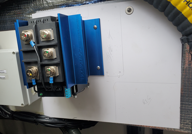
- E-Maax Pro 7 Regulators
- Electromaax Remote Rectifiers
- Alternator Shunts
- Genmaax 250A Alternators
- Class T Fuses and Holders
- Electromaax System Surge Protectors
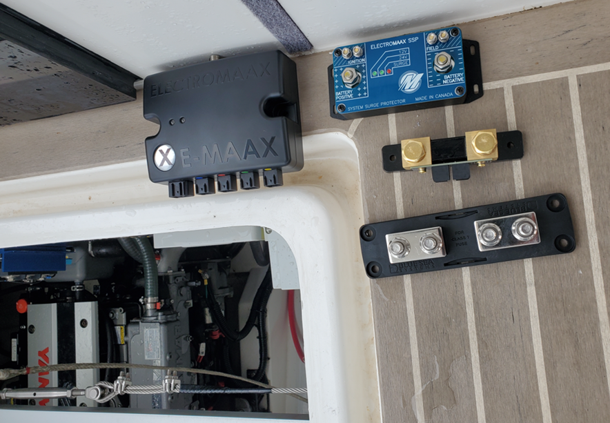
**Parts ready to install, note the water! Photo credit: Colin Chapman**
At the end of the work day, 8PM, we attached the regulator supply wires and were happily greeted with blinking LEDs indicating that they were powered up and in monitoring mode awaiting an ignition signal.
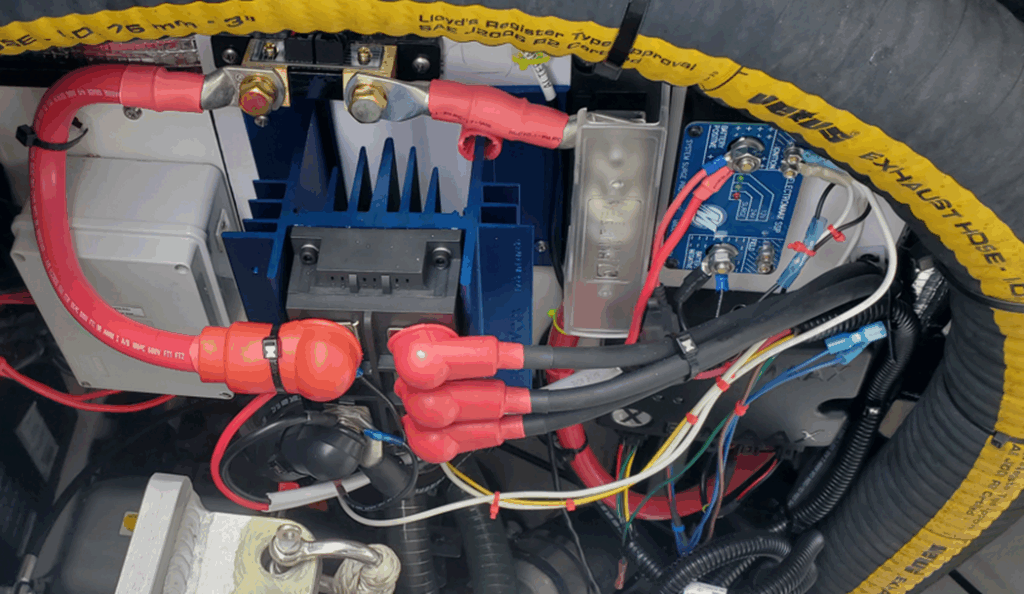
**Photo credit: Colin Chapman**
Testing
On the final day we only had a few hours before my flight home but we hadn’t turned on the engines yet. Would the system work for the first time?
We started up the engines, the E-MAAX Pro 7 regulators which are tethered together switched LEDs to blinking in the running mode and we were able to measure amperage flowing into the batteries. Success!
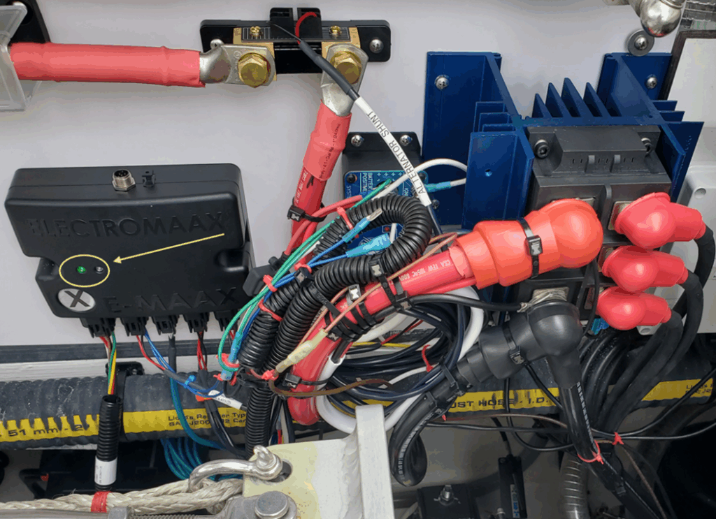
**A blinking success! Photo credit: Colin Chapman**
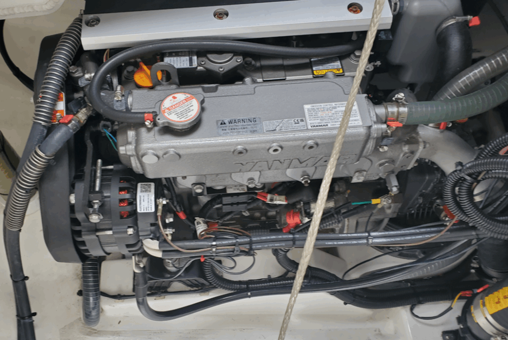
**New Genmaax 250A Alternator Mounted and wired. Photo credit: Colin Chapman**
**Lay out on strong board. Photo credit: Colin Chapman**
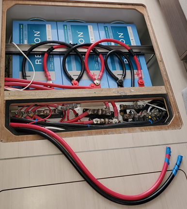
**Wires to the battery. Photo credit: Colin Chapman**
For any inquiries, please contact:
Email: support@electromaax.com
Website: www.electromaax.com