Our customer has a Beneteau 50 that has a Yanmar 4JH3-HTE 100 horsepower engine with an 80 amp Hitachi alternator. This is the configuration that came with the boat and they wanted to increase the charging capacity of the electrical system. They chose a 140 amp alternator and the serpentine belt kit.
The instructions seemed straightforward but I needed to have everything sorted as we live in Vancouver and the boat is in Greece.
I ordered the serpentine belt kit but there was a question I had in terms of the length of bolts as I have an engine driven refrigerator that runs off another pulley. We weren’t sure how that would be affected by the slightly different width of the serpentine belt pulley. The Electromaax guys sent me several lengths of bolts and I sourced several more locally in Vancouver. In the end I was able to reuse the existing bolts.
We got to the boat and the first order of business was to remove the existing alternator and belts. It turned out that the outer pulleys for the refrigerator compressor were tapped into the harmonic balancer that attaches to the crank.
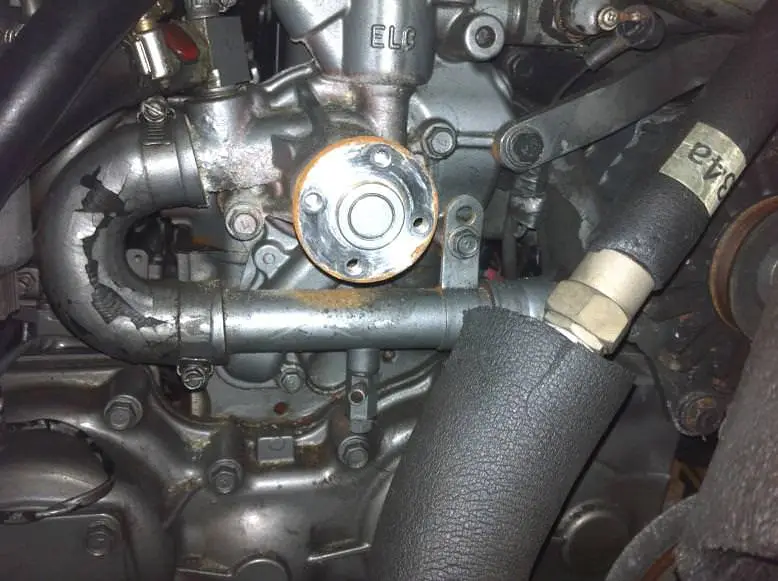
Figure The water pump exposed without the pulley on it.
The six hex head nuts holding the harmonic balancer on each unscrewed, then I pulled the Harmonic balancer off. There is a large nut at the end of the remaining pulley, and I removed that before I realized that the bottom crank pulley simply fits over the top of the existing pulley on the 4JH3-HTE. After putting on liberal amounts of tef gel, I re-affixed the large bolt back on the crankshaft and carefully aligned the holes and slid the bottom serpentine belt pulley onto the crankshaft.
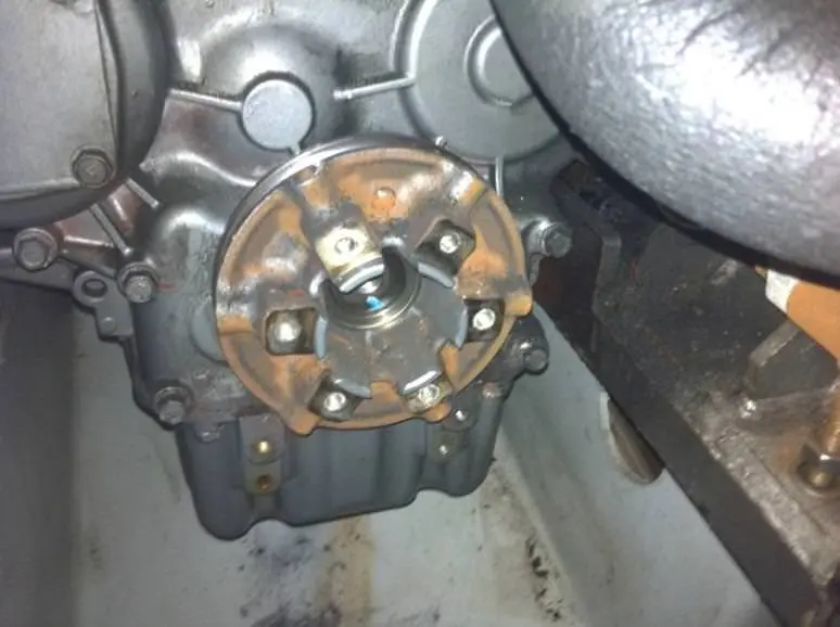
Figure : Crankshaft Pulley Exposed
To facilitate its installation, I used two bolts to help install the pulley, and then removed them placing the harmonic balancer on and tightening up the six bolts.
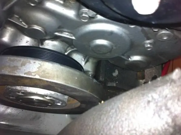
Figure : Harmonic balancer installed over top of the new pulley
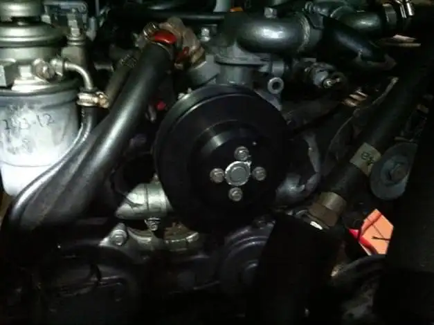
Figure : Water pump pulley installed. Note that I reused my existing fastners
I did not have any torque specifications so I tightened each bolt up and took up slack like you would on a tire – alternating the bolt I was tightening to one on the opposite side. It took several ½ turns of the wrench until every bolt was tight as the harmonic balancer seated onto the flanges. The blue Locktite Electromaax supplied will ensure that they will stay that way.
A couple of tips:
- Slacken the bolts on the water pump pulley while the alternator belt is still attached. Because the pump will spin freely, I needed to hookup the belt again to get the leverage to take the pump pulley off.
- Don’t undo the big 23mm nut that holds the Crankshaft onto the pulley as the pulley stays and the serpentine belt pulley simply sits on top of it.
Installing the Electromaax Alternator
My Hitachi alternator came off without a hitch and only had four connections to it.
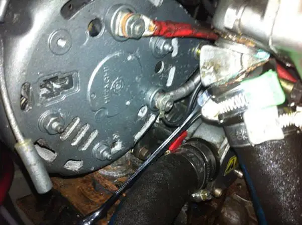
Figure : The old Hitachi Alternator – just four connections, one of which was undocumented and attached to the ground
Unfortunately the installation of the alternator could have been smoother with some prior fit-up.
My first challenge was the physical installation of the alternator onto the saddle connection. The Electromaax alternator needed a longer bolt by about 1” or 2cm than the one it replaced. The diameter of the bolt supplied by Electromaax was much smaller than the one I was replacing so I needed to use the bushings supplied. (they now supply this with every kit).
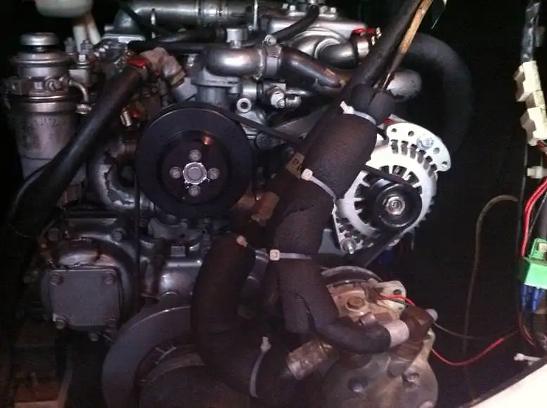
Figure : Note the bushing pressed into the foot.
The directions on the Balmar 614 are a little fuzzy for someone that doesn’t install alternators for a living. I hooked up the field wire to the regulator, the tachometer wasn’t needed, the wiring harness connected in directly and I put a new Ancor 2/0 cable between it and the house battery bank through a 225 amp Blue Sea Systems Fuse of course – no voltage drop there!
We ran the engine and the Balmar regulator said it was putting out 12.8 volts, verified at the battery with my multimeter. I can tell you that for a guy that has spent several thousands of dollars (new battery charger, inverter, the alternator, the serpentine belt kit, 75 feet of new 2/0 Ancor wiring) plus installing the kit in 35 degree heat, I was a bit apoplectic.
I figured that it must be something with the configuration so I tried re-reading the installation instructions and researching it on the Internet and came up blank.
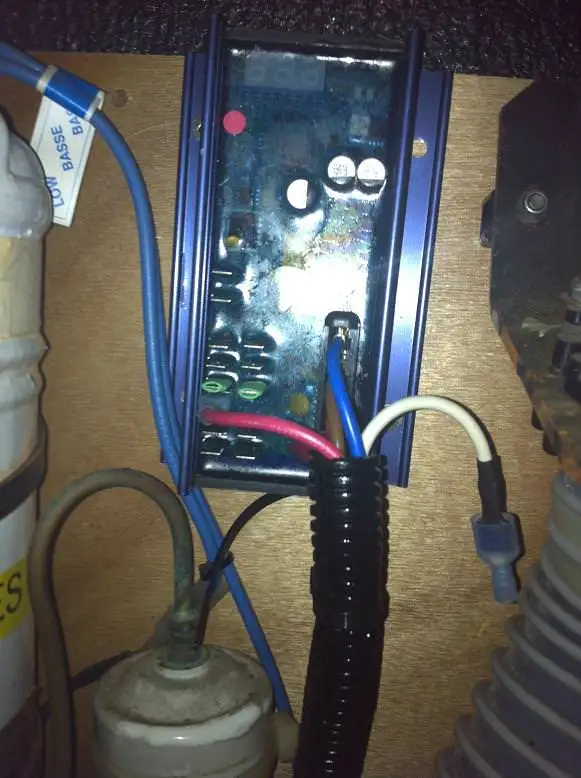
Thankfully the Electromaax support guys were in the office and the time-zones worked so I called them and Darren answered and told me I needed to run a 12 volt wire from the positive battery post onto pin 7 of the Balmar 614 Regulator or it won’t power itself up. I had a test wire rigged up within ten minutes and bingo … 13.8 volts and 60 amps going into my batteries. Wahoo! Thanks guys. I then installed the Balmar regulator in a place above the engine near where a number of other electronic elements are. While I need to open up one of the engine hatches to read it, it’s one of those things you don’t really need to see on a regular basis, so I don’t think it’s a major problem.
Finally I needed to figure out what was going on with my bow thruster and anchor windlass. Pouring through the boat wiring documents and the Hitachi alternator documents from Yanmar there was an undocumented wire. It was however connected to ground, so let’s start there, connect it to ground (only after looking at it, testing it with the multimeter,
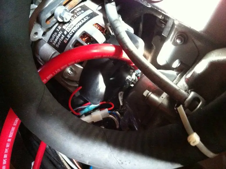
getting continuity to the grounding bolt) we gave it a try – and problem number 2 solved.
Now we are putting out lots of volts and amps into our main battery pack. I also threw away my old battery isolator (consumer of most of a volt) and installed a Balmar digital duo charge instead. My Yanmar cranks for ½ second before it lights so the loads on the starter battery are minimal. This solution seemed simpler than wiring the two battery banks separately.
The final change was getting my engine driven refrigerator belt adjusted. It turned out to be fairly simple as the distance that it changed corresponded to the second pulley, so instead of putting the refrigerator on the inner pulley it is now on the outer pulley. How simple is that.
Now that I have it all installed we are pushing 13.8 volts at as low as 1000 RPMs, so when we are powering we are always adding to our battery bank. Also, by eliminating the old battery isolator, all these volts and amps make it into our house battery bank. When we are using our 1500watt anchor windlass or 1500 watt bow thruster we are still pushing 12.8 volts into the house batteries – so no matter what the consumption of power, our batteries are safe from depletion.
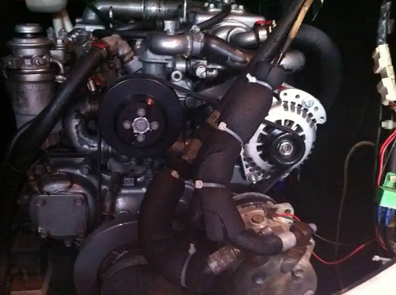
Figure : Final installation is very clean. The engine driven refrigerator is in the foreground powered by a 12mm belt in front of the harmonic balancer
Considering that I didn’t have access to the boat during the planning and this was the first time I have installed an alternator or an external regulator, it wasn’t very hard. Had I done a better job of the dry-fit it would have been less frustrating (though it is hard to know exactly what parts you need until you get there).
The serpentine belt kit was beautifully machined and fit perfectly, and was very easy to install. The alternator with very minor modifications fit perfectly into the existing saddle. The regulator was a bit confusing as the directions seemed to neglect to tell you to run a power lead to it – though there is a blade connector and a fused battery connection to give you a clue. The Electromaax support team were there right away on the phone to help and solved my problems.
All in all it was a very good investment of a couple of hours and well within the skill level of someone that does some wrenching like installing belts or oil changes
Serpentine Belt Kit
1.5 hours
Ratchet set with allen key sockets and metric sockets. 15mm spanner for removing the existing alternator.
Alternator Installation
2.0 hours, could have been 1.0 hours if bushings fit properly
Crimper for 2/0 cable, metric spanners for tightening saddle and foot, drill and bits for widening bushing
Regulator installation
1.5 hours
Wire for the regulator power, Ancor blade connectors, Ancor butt connectors, Ancor ring connectors, drill and bits for mounting. Telephone for calling support.